 |
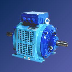
Lift motors of range ATM |
|
The three-phase asynchronous lift motors are intended for drives of lift machines.The three-phase asynchronous squirrel-cage motors of range ATM are equipped with degrees of protection IP10 and IP20, internal cooling IC01 and with an option of adding supplementary cooling for higher number of starts. The employed insulation system corresponds to the thermal insulation class F. Construction parts are made of cast iron. Terminal box and its cover are of aluminum alloy. In basic design, the terminal box is situated on top of the motor, with an option of turning the terminal box through 180o. Mechanical design of the frame enables the terminal box to be transferred to the right or left side of the motor. The motors feature low noise and low severity of vibration. Mounting dimensions comply with the standard IEC 60072-1
1- innovation number :if not stated - with sleeve
bearings 1 - with rolling-contact bearings Each modification and different design of the motor is indicated with a clear-cut code number stated in the rating plate of motor.
The lift motor operates under the ambient conditions free from a risk of dangerous concentration of inflammable gases or vaporous, or a risk of setting[up] the atmosphere of fire hazard owing to inflammable powders. Other types of atmosphere must be agreed on with the manufacturer. Loading, rated output, number of poles [up] One-speed motors are intended for intermittent periodic duty with starting, duty type S4 according to EN 60034-1. Number of starts, cyclic duration factor and additional moment of inertia are stated in the tables. Double-speed motors are intended for intermittent periodic duty with starting and electric breaking, duty type S5 according to EN 60034-1. Number of starts, cyclic duration factor and additional moment of inertia are stated in tables. Running time of the low-speed part at cyclic loading is 3 s at least. The machine dimensions are set so as to prevent the temperature rise in winding from exceeding permissible limit of the thermal insulation class F, provided the motor is loaded at its rating, under duty cycle and additional moment of inertia Jad. The low-speed part of motor is loaded with reference torque. The basic types of constructions of the motors are IM1002 - foot-mounted and IM3002- flange-mounted according to IEC 60034-7 and IEC 60072-1. By agreement with the manufactures, also the types of constructions with one shaft end - IM1001, IM3001 or shaft protection for 2nd shaft end is available. Bearings, axial clearance of rotor [up] Motors of basic design are made with sleeve bearings. The ring lubrication of motor is embedded in bearing cells. Motors with rolling-contact bearings are equipped with permanent grease-fillings. By axial clearance the difference of rotor end positions is meant. The values of axial clearance of the rotor are as follows:
The clearance can be eliminated with distance rings. By agreement with the manufacturer, the motor can be supplied with one set (2 pieces) of distance rings at extra charge. The terminal box consists of the box itself and detachable cover attached with screws. The terminal box is made with the degree of protection IP44. On the inner side of the cover there is the wiring diagram of motor. The terminal box can be turned through 180o. On request also the motors with side-positioned terminal box can be delivered. The terminal box is attached to the frame lugs, and the number of terminals corresponds to the respective design. The space taken[up] by the terminal box is separated from that of the motor. The motors are equipped with thermal protection which provides a complementary protection and prevents the winding from exceeding the permissible temperature rise. Each phase of winding comprises one temperature sensor. One-speed motors are equipped with 3 sensors which are connected across the terminals T1 and T2. In two-speed motors the winding accommodates 6 sensors which are connected in series and led out to the terminals T,T1,T2. In basic connection the relay of thermal protection is connected across the terminals T1 and T2. In case of failure of any of the sensors, the relay can be connected across the terminals T,T1 or T,T2 to exclude the faulty triad. For the protection of winding the following types of temperature sensors can used. a/ Thermal protection with PTC thermistors b/ Bimetallic thermal protection Motors with external fan cooling have in stator winding am embedded thermal protector which will trigger the external fan if the temperature of stator winding is in range of 85 - 105oC. Subsequent installation of the external fan in the customer's seat: Process of mounting: Remove the fan louver and attach an external fan to its place. Motor outlets of the external fan are connected across the terminal board in compliance with the indicated wiring diagram. [up]
The motors are delivered against an order and subsequent contract approved by both parties. Delivery term for motors of standard design is 6 weeks. Motors made by special requirements in compliance with the catalogue can be delivered in 8 weeks Guarantee for the motors is 24 months from the day of putting into operation,
anyway 27 months from the day of dispatching them from the factory at longest.
The motors are covered with water-resistant foil and laid on wood transportation
pallet. Motors with sliding bearings are delivered without an oil filling in bearings.
Free shaft ends and metal, clean machined surfaces of the motor frame are protected with
preserving varnish. When stowing the transportation pallets with motors on one another, we
must avoid transferring the weight of the upper pallet onto the motors resting on the
bottom pallet. Data to be quoted in orders [up]
Dealership in Czech republic [up] dealer : Vážní ul. 500 03 HRADEC KRÁLOVÉ, Contact: Mrs. Krsek, Before setting up, the bearing cells have to be filled with OL-46 oil or with
oil of other type specified by the manufacturer of motor (ESSO type NUTO H 46). The oil
filling volume is to be watched on an oil level gauge. The oil should be filled[up]
to one
half of the oil level gauge. All work on motor is performed in a rest and denier gazed condition (with the exception of some work items to be done un deer voltage at revising the electrical parts of the motor), and the observance of all relevant safety rules specified by operative technical standards is required. At any time it is necessary to recheck whether the guard wire is duly connected and whet her the live parts are without voltage, and to prevent an accidental switch on. At revising, it is necessary to ensure that all connecting terminals inside the terminal box are duly tightened. In case of need they must be tightened to avoid warming up the connection due to contact resistance. The first oil filling exchange should be carried out after a two-month service, and each subsequent exchange after 1500 service hours, anyway, once in a half-year term at least.
|
| ||||||